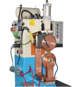
Seam Welding Machines Manufacturer & Exporter
With the aid of our quality-oriented professionals, we have brought forward Seam Welding Machine. These machines are offered with the assurance of optimum performance and can be used for longer time periods. These machines are used to cater to the diversified industrial applications and are our recommended offerings. Applicable for seam welding purposes, these machines are our recommended products.
All the seam-welding techniques require high thermal energy input to weld work pieces together. Contrary to a spot weld, a seam weld is a continuous weld in various welding geometries such as fillet and butt welds. In this chapter, only seam-welded joints are considered, whereas the analysis and behavior of spot-welded joints is a specific area that has been treated differently
Seam welding uses a wheel-shaped electrode (Fig. 9.4) to make either a series of overlapping spot welds to form a continuously welded and leak tight seam or a number of spot welds spaced apart – roll-spot welding. The requirements on electrodes and surface finish are the same as for spot welding. The shunt effect of the closely spaced nuggets and the short weld times mean that higher currents are necessary than for spot welds.
Higher welding forces will be needed for harder alloys and lower values for softer alloys. Welding parameters for three phase frequency converter units are similar to those in Table 9.4 except that welding current needs to be increased by between 0.5 and 2.5 times, the higher values for the thicker materials.
Pick-up on the electrode wheel can be a problem and may require the wheel to be cleaned after only one revolution. Mechanised cleaning systems that remove the contamination in-process by wire brushing or abrasive means have been successful in maintaining continuous production.
| Item | Unit | RPL 250 | RPL 400 | TCR 250 | TCR 400 |
Rated Supply |
V |
400+-10% |
400+-10% |
400+-10% |
400+-10% |
Phase |
Ph. |
2 |
2 |
2 |
2 |
Frequency |
Hz. |
50 |
50 |
50 |
50 |
Load |
KVA |
100 |
150 |
200 |
100 |
Welding Current |
A |
19000 |
28000 |
39000 |
17000 |
Standard Stoke |
mm. |
100 |
100 |
100 |
100 |
Transformer & Electrode |
X |
Water Cooled |
Water Cooled |
Water Cooled |
Water Cooled |
Water Supply |
L/min. |
30 |
30 |
30 |
30 |
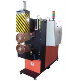
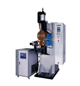
Seam welding is used in the same way as spot welding, and operates on essentially the same principle. The difference is that two wheel-shaped electrodes are used, rolling along (and usually feeding) the work piece.
The two wheels should be of the same size, in order to prevent the part from being deflected towards one of them. The actual contact profile can be designed in a number of ways, in order to suit the shape of the part to be welded. The current may flow continuously while welding is being carried out, or intermittently to produce a series of spots that are so closely positioned as to produce a single, continuous weld. An unavoidable problem of seam welding is that some of the current 'leaks' through the completed weld.
As the electrode rollers rotate, they do not need to be lifted between each spot, as with spot welding. If the weld does not have to be continuous, seam welding can be used to position spots at regular distances from each other. That means that seam welding can be carried out quicker than ordinary spot welding.
All the seam-welding techniques require high thermal energy input to weld work pieces together. Contrary to a spot weld, a seam weld is a continuous weld in various welding geometries such as fillet and butt welds. In this chapter, only seam-welded joints are considered, whereas the analysis and behavior of spot-welded joints is a specific area that has been treated differently and will be discussed in Chapter 11.
During the service life of welded structures exposed to various service loading conditions, welded joints are usually the potential fatigue failure sites due to the highest stress concentration areas and altered material properties. Thus, engineers and scientists are always interested in understanding fatigue characteristics of the welded joints, and are trying to develop analytical tools to estimate fatigue lives of welded joints. However, prediction of fatigue life of welded joints is frequently complicated and inaccurate because many parameters affect the fatigue life of welded joints.
Welding strongly affects the materials by the process of heating and subsequent cooling as well as by the fusion process with additional filler material, resulting in inhomogeneous and different materials. Furthermore, a weld is usually far from being perfect, containing inclusions, pores, cavities, undercuts, and so on. The shape of the weld profile and nonwelded root gaps creates high stress concentrations with varying geometry parameters. Moreover, residual stresses and distortions due to the welding process affect the fatigue behavior.
In view of the complexity of this subject on fatigue life prediction models of seam-welded joints and the wide area of applications, it is not surprising that several analytical approaches exist and none of them could account for the aforementioned process variables. Therefore, it has been an ongoing research area of interest to all the engineering disciplines to improve the life predictive capability for seam-welded joints.
Due to the vast amount of relevant literature, this chapter will present only Dong's and Fermer's structural stress approaches (Dong, 2001a,b; Fermer et al., 1998) and the notch pseudo stress approach because the three approaches have been coded in some commercial fatigue analysis modules as one of the Computer Aided Engineering (CAE) tools used in automotive engineering. Refer to the book by Radaj et al. (2006) for a detailed review of all other methods. However, this chapter will start with an introduction of the parameters affecting the fatigue life of welded joints to help you understand the possible sources of the variability of fatigue data.
Special Features
Technical Specifications Of Seam Welders
MODEL |
UNITS |
TSM-50 |
TSM-75 |
TSM-100 |
TSM-150 |
TSM-200 |
Nominal capacity at 50% duty cycle |
KVA |
50 |
75 |
100 |
150 |
200 |
Continuous rating of transformer |
KVA |
35 |
55 |
70 |
110 |
140 |
Supply voltage 1 Phase 50 Hz. |
V |
415 |
415 |
415 |
415 |
415 |
Switch Fuse |
A |
125 |
200 |
250 |
400 |
500 |
Throat Depth Std. |
mm |
460 |
600 |
600 |
600 |
600 |
Welding Capacity : Mild Steel |
mm |
1 + 1 |
1.25 + 1.25 |
1.6. + 1.6 |
2 + 2 |
2.5 + 2.5 |
Dimensions Overall : Height |
mm |
1900 |
1900 |
1900 |
1900 |
2000 |
Width |
mm |
900 |
950 |
1000 |
1000 |
1200 |
Length |
mm |
1500 |
1600 |
1750 |
1750 |
1750 |
Weight Appx with Standard Throat Depth |
Kgs. |
1100 |
1300 |
1600 |
1900 |
2200 |
Resistance seam welding is a process that produces a weld at the faying surfaces of two similar metals. The seam may be a butt joint or an overlap joint and is usually an automated process. It differs from flash welding in that flash welding typically welds the entire joint at once and seam welding forms the weld progressively, starting at one end. Like spot welding, seam welding relies on two electrodes, usually made from copper, to apply pressure and current. The electrodes are often disc shaped and rotate as the material passes between them. This allows the electrodes to stay in constant contact with the material to make long continuous welds. The electrodes may also move or assist the movement of the material.
A transformer supplies energy to the weld joint in the form of low voltage, high current AC power. The joint of the work piece has high electrical resistance relative to the rest of the circuit and is heated to its melting point by the current. The semi-molten surfaces are pressed together by the welding pressure that creates a fusion bond, resulting in a uniformly welded structure. Most seam welders use water cooling through the electrode, transformer and controller assemblies due to the heat generated.
Seam welding produces an extremely durable weld because the joint is forged due to the heat and pressure applied. A properly welded joint formed by resistance welding can easily be stronger than the material from which it is formed.
A common use of seam welding is during the manufacture of round or rectangular steel tubing. Seam welding has been used to manufacture steel beverage cans but is no longer used for this as modern beverage cans are seamless aluminum.
There are two modes for seam welding: Intermittent and continuous. In intermittent seam welding, the wheels advance to the desired position and stop to make each weld. This process continues until the desired length of the weld is reached. In continuous seam welding, the wheels continue to roll as each weld is made.
To meet diverse requirements of our clients in the best possible manner, we are offering a comprehensive range of Seam Welding Machine.
Applications: Automobile Products Sheet Metal Components Strip Processing Industries Transformer Radiators Drums, Barrelss,Containers.
Specification: Available in circumferential, longitudinal & universal types
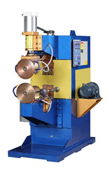
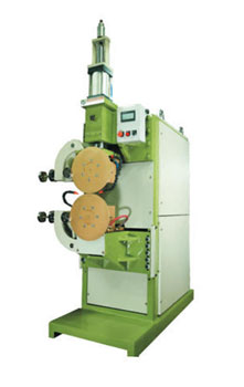
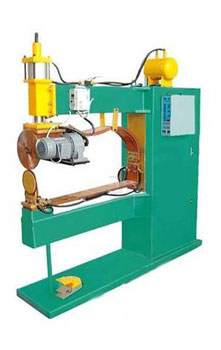
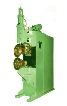
Specifications:
Model >> Longitudinal |
SL-50 to SL-200 |
Model >>Circumferential |
SL-50 to SC-200 |
Rating KVA @ 50% duty cycle |
50 to 200 |
Upper electrode cylinder stroke max. (mm) |
50 |
Vertical adjustability of ram (mm) |
50 |
Max available +/- 10% @ 460 throat depth0 (KAmps) |
Up to 30 |
Max.Electrode force @5.62 kg/cm sq. (Kgf) |
440 up to 990 |
Seam Welding Machine is precision built, with careful design and robust construction, suitable for long trouble free service. Each machine is submitted to rigorous proving tests before delivery is made, in order that the machine may be ready for immediate installation and operations at customer's works.
These pneumatically operated seam welding machines are used for an uninterrupted weld run for impeccable seam welding of the drums. Featuring modern design, these seam welding machinesare air operated and have a variety of alternative features for ensuring efficient usage in every kind of seam welding application within the range. We manufacture, supply and export seam welding machines in various specifications to our clients.
